...
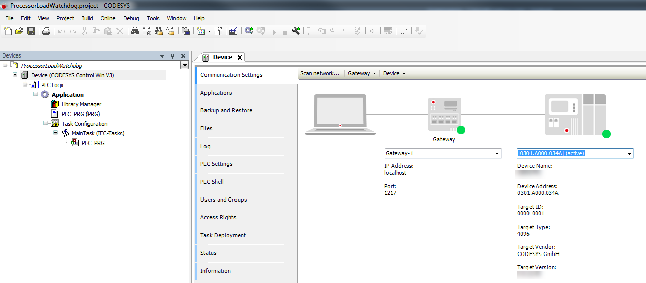
This watchdog must be activated in
...
the CODESYSControl.cfg configuration file.
| Info |
|---|
Depending on the runtime, the configuration file is located in the following place: Location of the configuration file configuration file. |
The limit is defined
...
in the CmpSchedule section.
Experience has shown that communication problems occur more often in the case of controllers under high loads.
| Expand | ||
|---|---|---|
| ||
|
...
|
...
|
...
|
...
|
...
| Column | ||
|---|---|---|
| ||
Declaration |
...
| width | 93 |
|---|
|
...
|
...
| theme | Confluence |
|---|
...
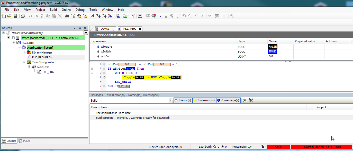
VAR
    xToggle   : BOOL;
    xSwitch   : BOOL;
    udiCnt    : UDINT;
END_VAR
...
| Column | ||
|---|---|---|
| ||
Implementation |
...
| width | 93 |
|---|
...
| theme | Confluence |
|---|
...
|
|
...
|
...
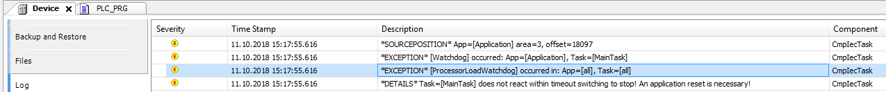
The following entries are located in the PLC log:
...
Processor load and Multicore
With the introduction of multicore support (since V3.5.SP13), the processor load is calculated as the average of all CPUs.
This also applies for the runtime license without multicore support.
Therefore, the following situation results in the case of an active infinite loop for an 8-core processor:
...
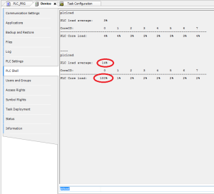
To trigger the watchdog, the limit has to be set to approximately 10% in the ini file.
...
| theme | Confluence |
|---|
|
...
|