Connecting to a WAGO Controller via Modbus (TCP)
Hardware
- 1x WAGO fieldbus coupler 750-352/000-001
- 1x digital input terminal 750-401
- 1x digital output terminal 750-504
- 1x end terminal 750-600
Requirements for the WAGO controller
- Assign the IP address (for example with the tool WAGO Ethernet Settings).
- Activate Modbus protocol (TCP) (for example with the tool WAGO Ethernet Settings → Protocol).
- Get the manual for the fieldbus coupler.
Requirements for CODESYS
- Create a standard project and define your device (for example CODESYS Control Win V3).
Scan the network and select the device.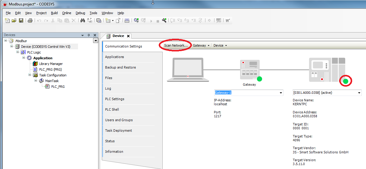
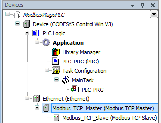
- In the device tree, add an Ethernet adapter, a Modbus_TCP_Master, and a Modbus_TCP_Slave.
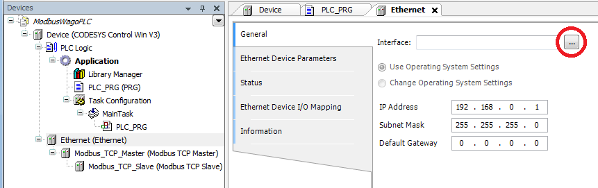
Settings on the Ethernet adapter
Tab General
Define the network interface to be used.
| Note |
|---|
If a target system is not defined yet, then the error message "Gateway not configured" is displayed. |
Settings on Modbus_TCP_Master
Tab General
Activate the automatic establishment of a connection after interruption.
Settings on Modbus_TCP_Slave
Tab General
Specify the IP address of the WAGO controller and leave the Unit ID blank.
For Modbus via TCP/IP, the slave is identified by means of the IP address.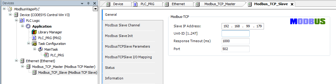
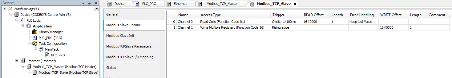
Tab Modbus Slave Channel
Create a channel for reading the input adapter: 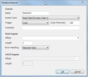
Create a channel for switching the contacts of the output adapter: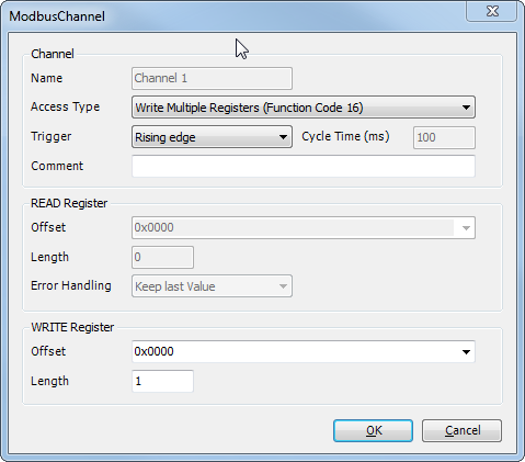
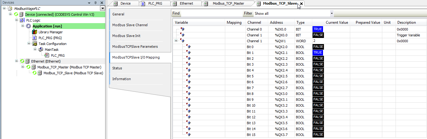
Tab Modbus TCP Slave I/O Mapping
So that the Modbus addresses are updated even without variable mapping, you have to activate this explicitly: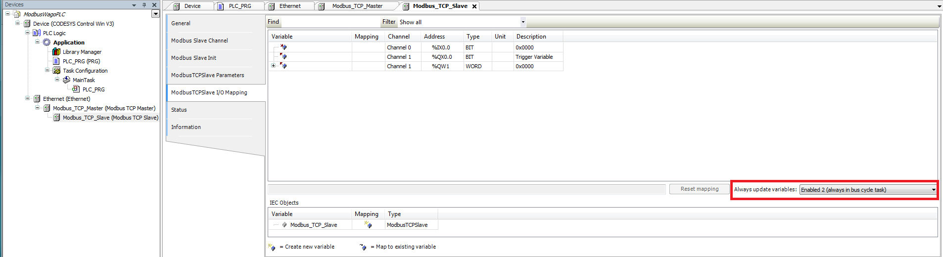
Download the project to the controller and start it