Hardware
- 1x WAGO fieldbus coupler 750-352/000-001
- 1x digital input terminal 750-401
- 1x digital output terminal 750-504
- 1x end terminal 750-600
Requirements for the Wago controller
- Issue the IP address (e.g. using the tool WAGO Ethernet Settings).
- Activate output variables (e.g. using the tool WAGO Ethernet Settings → Ethernet/IP).
- Procure the manual for the fieldbus coupler.
- Download the current EDS file for the device from the WAGO website.
Requirements for CODESYS
- Install the Wago EDS file via Tools → Device Repository... → Install...
- Create a standard project and define your own device (e.g. CODESYS Control Win V3) Scan the network and select the device.
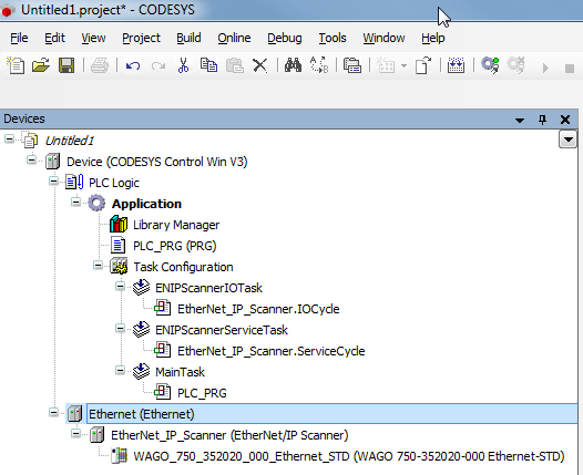
- Insert an Ethernet adapter, an Ethernet/IP scanner and a Wago fieldbus coupler in the project.
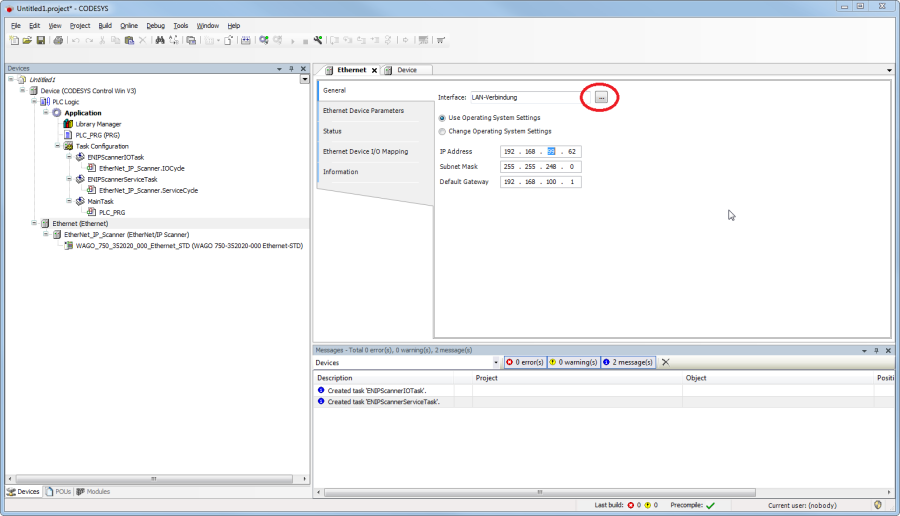
Settings on the Ethernet adapter
- Define the network interface to be used.
Settings on the device
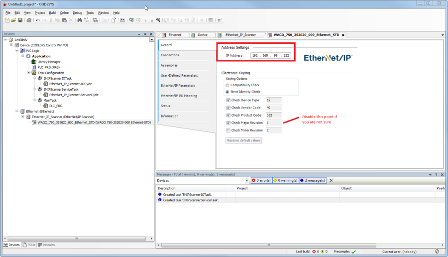
Tab General
- Enter the IP address of the device.
| Note |
|---|
The option Check Major Revision can be deactivated in order to avoid errors. |
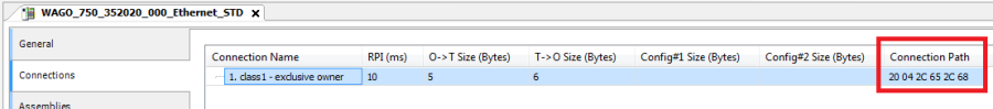
Tab Connections
- Through the EDS file a standard connection is created with the connection path 20 04 2C 65 2C 68.
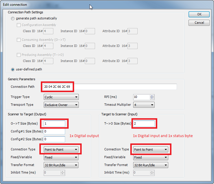
From the Wago manual (WAGO Assembly Instances) it can be seen that 0x65 (101) in the connection path means the following: 0x65 (101) → for analog and digital output data Since we are only using a digital output terminal, you need to change this value to 0x66 (102): 0x66 (102) → for digital output data Also, change the value 0x68 (104) → for analog and digital input data with status byte to 0x69 (105) for digital input data with status byte. This produces the following connection path: 20 04 2C 66 2C 69 To be able to change the connection path you have to delete the existing connection and add a new one. Set the new connection to generic connection (freely configurable) and the settings for the connection path to user-defined path. In addition, make the following settings:
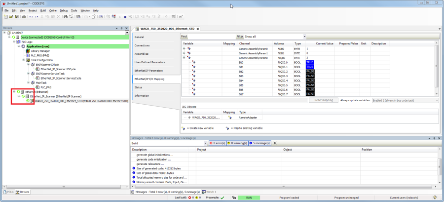
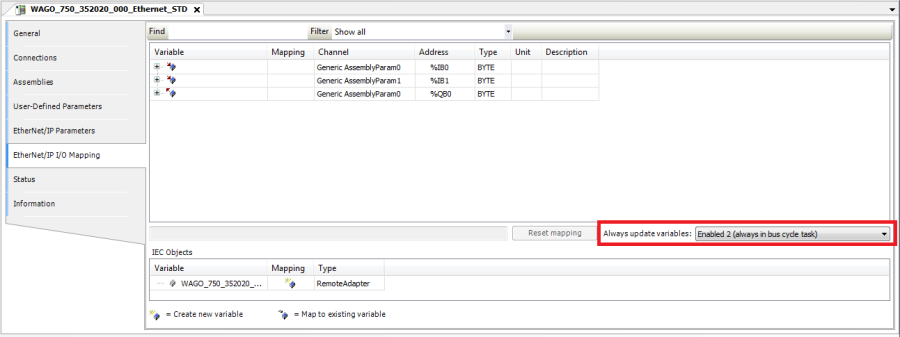
Tab Ethernet/IP I/O mapping
- So that the values from the bus are displayed without variable connection, set updating to Activated 2 (always in the bus cycle task).
Loading the project to the controller and starting it