The CODESYS controller supports only one IP-based link.
Hardware
- 1x ABB power supply: SV/S 30.640.5.1
- 1x ABB IP interface: IPR/S 3.1.1
- 1x ABB switch actuator: SA/S 4.6.2.1
- 1x Gira button BA 2f 1 point: 5161 30
Requirements for ETS
The ETS is available in Version 5.6.5 Build 1109.
- Installation of the product files (*.knxprod) for the devices listed above
- Installation of the product file KNX_CDS_Gateway.knxprod for the CODESYS controller
The file is located in the CODESYS KNX-Package (<installation path>\CODESYS KNX\<version>\ETS5\KNX_CDS_Gateway.knxprod).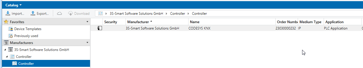
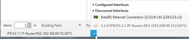
- IP interface specified as communication interface
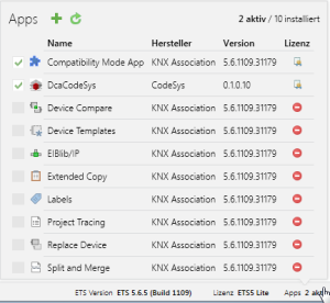
- Installation and activation of the "DcaCodeSys" plug-in.
The file is located in the CODESYS KNX Package (<installations path>\CODESYS KNX\<version>\ETS5\DcaCodeSys.etsapp). - Installation and activation of the "Compatibility Mode App"
- A physical address has been assigned to the devices listed in hardware.
Switch actuators
Button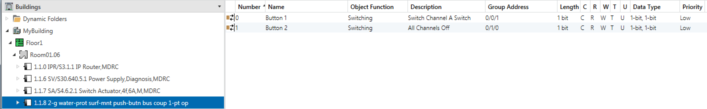
Preparing the CODESYS controller
- Make sure that the controller supports KNX links.
- In Version 3.5 SP14 and later, the Control SL products support the KNX stack (no components have to be added).
This does not apply to CODESYS Control WIN (the KNX component has to be added in CODESYSControl.cfg). - Insert the components in the CODESYSControl.cfg file:
[ComponentManager]
Component.X=CmpKNXStack.dll
Preparation in the CODESYS project
- Create a "Standard project" and select CODESYS Control Win V3 as the device.
- Define the target system by means of the Network Scan.
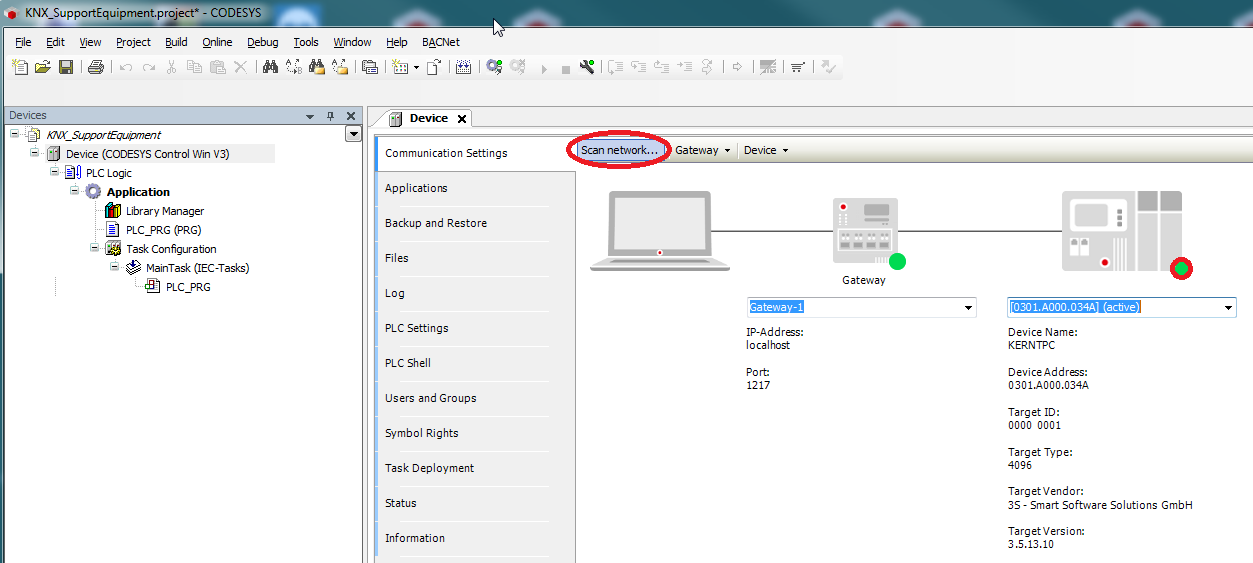
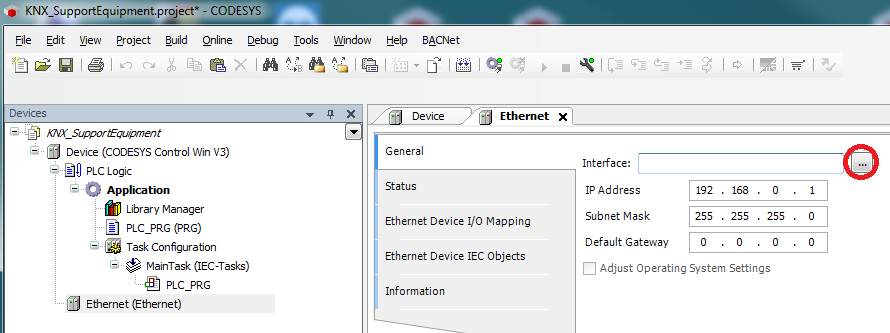
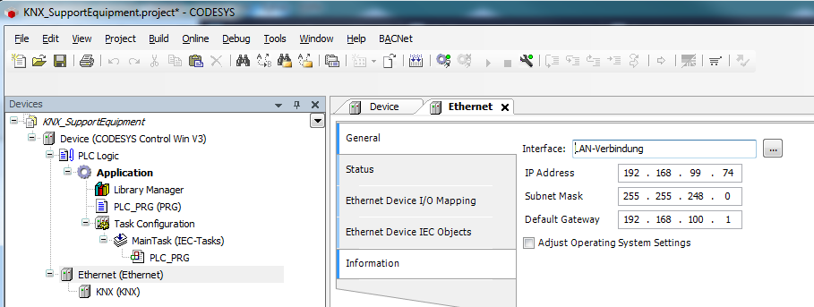
Insert an Ethernet adapter into the device tree and specify the interface to be used.
If a target system has not been defined yet, then the error message "Gateway not configured" is displayed.
- Insert a KNX below the Ethernet adapter in the device tree.
On the General tab, you can define any number of inputs.
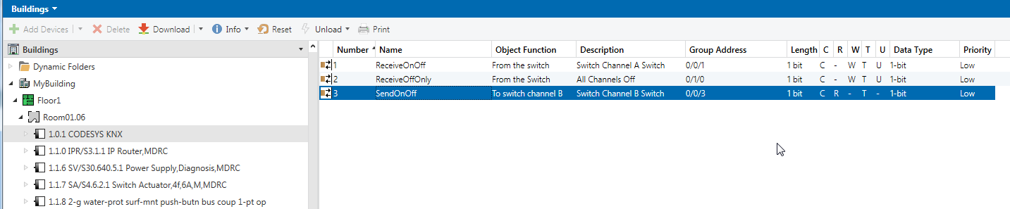
In the following, two input channels for receiving the telegrams of the button and one output channel for switching the actuator have been created: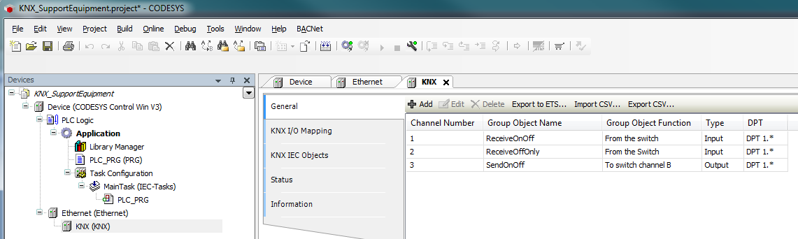
The KNX connection is limited to a total of 1000 inputs and outputs.
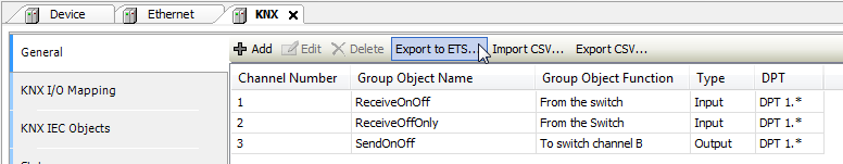
- You export this configuration to an XML format that can be read by the ETS.
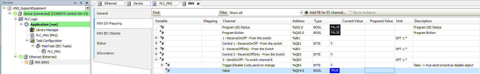
In the I/O mapping, data areas are created automatically for each channel.
In addition, two data points have been created, allowing the physical address to be assigned from the ETS software: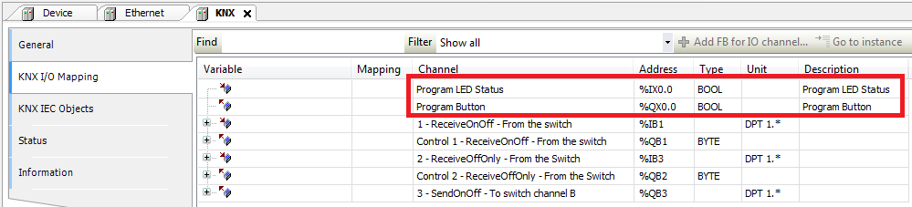
Integrating the CODESYS device in the ETS
- The controller can be added to the ETS project by means of the catalog.
Assign a physical address to the device: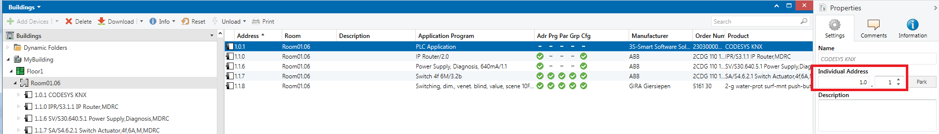
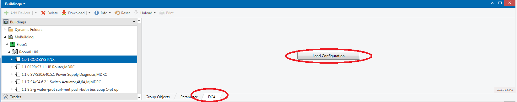
- On the DCA tab, the configuration previously exported in CODESYS can be read into the ETS.
- After the import, the inputs and outputs created in CODESYS can be connected with group addresses.
Transferring the ETS configuration to the controller
- As with any other device, the physical address must also be assigned to the CODESYS controller.
Therefore the data point must be set after the request in the ETS: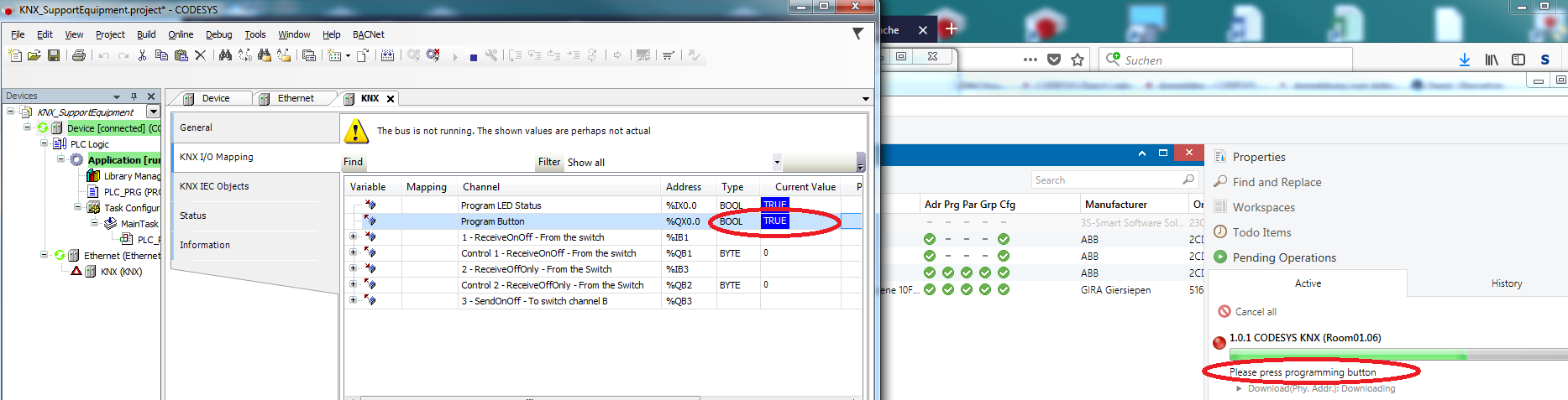
If this is done promptly, then the assignment of the physical address is documented in the ETS.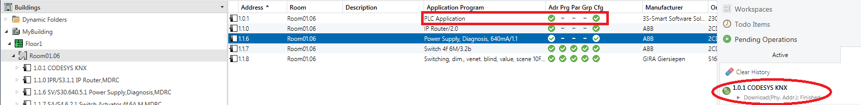
Because the controller does not have a valid program yet, it must still be downloaded from the ETS.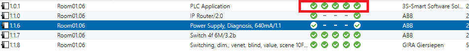
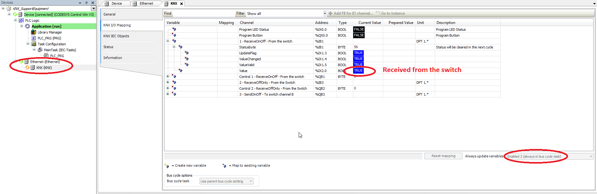
Likewise, the actuator (channel B) can be switched by means of I/O mapping.